- 您现在的位置:买卖IC网 > Sheet目录308 > ADUM1300BRW (Analog Devices Inc)IC DIGITAL ISOLATOR 3CH 16-SOIC
ADuM1300/ADuM1301
Data Sheet
DIN V VDE V 0884-10 (VDE V 0884-10):2006-12 INSULATION CHARACTERISTICS
These isolators are suitable for reinforced electrical isolation only within the safety limit data. Maintenance of the safety data is ensured by
protective circuits. The asterisk (*) marking on packages denotes DIN V VDE V 0884-10 approval for 560 V peak working voltage.
Table 11.
Description
Conditions
Symbol
Characteristic
Unit
Installation Classification per DIN VDE 0110
For Rated Mains Voltage ≤ 150 V rms
For Rated Mains Voltage ≤ 300 V rms
For Rated Mains Voltage ≤ 400 V rms
Climatic Classification
Pollution Degree per DIN VDE 0110, Table 1
I to IV
I to III
I to II
40/105/21
2
Maximum Working Insulation Voltage
V IORM
560
V peak
Input-to-Output Test Voltage, Method B1
V IORM × 1.875 = V PR , 100% production test, t m = 1 sec,
V PR
1050
V peak
partial discharge < 5 pC
Input-to-Output Test Voltage, Method A
V IORM × 1.6 = V PR , t m = 60 sec, partial discharge < 5 pC
V PR
After Environmental Tests Subgroup 1
896
V peak
After Input and/or Safety Test Subgroup 2
V IORM × 1.2 = V PR , t m = 60 sec, partial discharge < 5 pC
672
V peak
and Subgroup 3
Highest Allowable Overvoltage
Transient overvoltage, t TR = 10 seconds
V TR
4000
V peak
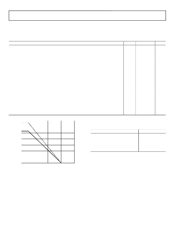
Safety-Limiting Values
Maximum value allowed in the event of a failure
(see Figure 3)
Case Temperature
Side 1 Current
Side 2 Current
T S
I S1
I S2
150
265
335
°C
mA
mA
Insulation Resistance at T S
V IO = 500 V
R S
>10 9
Ω
350
300
RECOMMENDED OPERATING CONDITIONS
Table 12.
250
200
SIDE #2
Parameter
Operating Temperature (T A ) 1
Operating Temperature (T A ) 2
Supply Voltages (V DD1 , V DD2 ) 1, 3
Rating
?40°C to +105°C
?40°C to +125°C
2.7 V to 5.5 V
150
100
SIDE #1
Supply Voltages (V DD1 , V DD2 ) 2, 3
Input Signal Rise and Fall Times
3.0 V to 5.5 V
1.0 ms
50
1
2
Does not apply to ADuM1300W and ADuM1301W automotive grade versions.
Applies to ADuM1300W and ADuM1301W automotive grade versions.
0
3
All voltages are relative to their respective ground. See the DC Correctness
and Magnetic Field Immunity section for information on immunity to external
0
50
100
150
200
magnetic fields.
CASE TEMPERATURE (°C)
Figure 3. Thermal Derating Curve, Dependence of Safety-Limiting
Values with Case Temperature per DIN V VDE V 0884-10
Rev. I | Page 20 of 32
发布紧急采购,3分钟左右您将得到回复。
相关PDF资料
ADUM1310BRWZ
IC ISOLATOR DGTL 3CH UNI 16-SOIC
ADUM1400WTRWZ
IC ISOLATOR DIG 4CH 125C 16SOIC
ADUM1412BRWZ-RL
IC ISOLATOR DGTL QUAD 16-SOIC
ADUM1420BRWZ-RL
IC ISOLATOR DGTL 4CH 28SOIC
ADUM1510BRWZ-RL
IC DIGITAL ISOLATOR 16-SOIC
ADUM2210TRIZ
ISOLATOR DGTL 2CH 16SOIC
ADUM2250ARIZ-RL
ISOLATOR DL I2C HOT-SWAP 16SOIC
ADUM2400CRIZ
ISOLATOR DGTL 4CH 16SOIC
相关代理商/技术参数
ADUM1300BRW-RL
制造商:Analog Devices 功能描述:Digital Isolator Logic 3-CH 10Mbps 16-Pin SOIC W T/R 制造商:Rochester Electronics LLC 功能描述:
ADUM1300BRWZ
功能描述:IC DIGITAL ISOLATOR 3CH 16-SOIC RoHS:是 类别:隔离器 >> 数字隔离器 系列:iCoupler® 标准包装:66 系列:iCoupler® 输入 - 1 侧/2 侧:2/2 通道数:4 电源电压:3.3V,5V 电压 - 隔离:2500Vrms 数据速率:25Mbps 传输延迟:60ns 输出类型:逻辑 封装/外壳:20-SSOP(0.209",5.30mm 宽) 供应商设备封装:20-SSOP 包装:管件 工作温度:-40°C ~ 105°C
ADUM1300BRWZ-RL
功能描述:IC DIGITAL ISOL 3-CH 16SOIC TR RoHS:是 类别:隔离器 >> 数字隔离器 系列:iCoupler® 产品培训模块:IsoLoop® Isolator 标准包装:50 系列:IsoLoop® 输入 - 1 侧/2 侧:5/0 通道数:5 电源电压:3 V ~ 5.5 V 电压 - 隔离:2500Vrms 数据速率:110Mbps 传输延迟:12ns 输出类型:CMOS 封装/外壳:16-SOIC(0.154",3.90mm 宽) 供应商设备封装:16-SOIC N 包装:管件 工作温度:-40°C ~ 85°C 其它名称:390-1053-5
ADUM1300CRW
功能描述:IC DIGITAL ISOLATOR 3CH 16-SOIC RoHS:否 类别:隔离器 >> 数字隔离器 系列:iCoupler® 产品培训模块:IsoLoop® Isolator 标准包装:50 系列:IsoLoop® 输入 - 1 侧/2 侧:5/0 通道数:5 电源电压:3 V ~ 5.5 V 电压 - 隔离:2500Vrms 数据速率:110Mbps 传输延迟:12ns 输出类型:CMOS 封装/外壳:16-SOIC(0.154",3.90mm 宽) 供应商设备封装:16-SOIC N 包装:管件 工作温度:-40°C ~ 85°C 其它名称:390-1053-5
ADUM1300CRW-RL
功能描述:IC DIGITAL ISOL 3-CH 16SOIC TR RoHS:否 类别:隔离器 >> 数字隔离器 系列:iCoupler® 产品培训模块:IsoLoop® Isolator 标准包装:50 系列:IsoLoop® 输入 - 1 侧/2 侧:5/0 通道数:5 电源电压:3 V ~ 5.5 V 电压 - 隔离:2500Vrms 数据速率:110Mbps 传输延迟:12ns 输出类型:CMOS 封装/外壳:16-SOIC(0.154",3.90mm 宽) 供应商设备封装:16-SOIC N 包装:管件 工作温度:-40°C ~ 85°C 其它名称:390-1053-5
ADUM1300CRWZ
功能描述:IC DIGITAL ISOLATOR 3CH 16-SOIC RoHS:是 类别:隔离器 >> 数字隔离器 系列:iCoupler® 标准包装:66 系列:iCoupler® 输入 - 1 侧/2 侧:2/2 通道数:4 电源电压:3.3V,5V 电压 - 隔离:2500Vrms 数据速率:25Mbps 传输延迟:60ns 输出类型:逻辑 封装/外壳:20-SSOP(0.209",5.30mm 宽) 供应商设备封装:20-SSOP 包装:管件 工作温度:-40°C ~ 105°C
ADUM1300CRWZ-RL
功能描述:IC ISOLATOR DGTL 3CH 16SOIC RoHS:是 类别:隔离器 >> 数字隔离器 系列:iCoupler® 标准包装:66 系列:iCoupler® 输入 - 1 侧/2 侧:2/2 通道数:4 电源电压:3.3V,5V 电压 - 隔离:2500Vrms 数据速率:25Mbps 传输延迟:60ns 输出类型:逻辑 封装/外壳:20-SSOP(0.209",5.30mm 宽) 供应商设备封装:20-SSOP 包装:管件 工作温度:-40°C ~ 105°C
ADUM1300WSRWZ
功能描述:IC ISOLATOR DIG 3CH 125C 16SOIC RoHS:是 类别:隔离器 >> 数字隔离器 系列:iCoupler® 产品培训模块:IsoLoop® Isolator 标准包装:50 系列:IsoLoop® 输入 - 1 侧/2 侧:5/0 通道数:5 电源电压:3 V ~ 5.5 V 电压 - 隔离:2500Vrms 数据速率:110Mbps 传输延迟:12ns 输出类型:CMOS 封装/外壳:16-SOIC(0.154",3.90mm 宽) 供应商设备封装:16-SOIC N 包装:管件 工作温度:-40°C ~ 85°C 其它名称:390-1053-5
